ByteByteGo Newsletter
Figma Design to Code, Code to Design: Clearly Explained
ByteByteGo
Apr 14, 2026
Figma Design to Code, Code to Design: Clearly Explained
Source: ByteByteGo Newsletter · Author: ByteByteGo · Date: 2026-04-14 · Original article
Turning a Figma design into working code — and keeping the two in sync as the code evolves — is one of the most common chores in frontend work, and one of the hardest to automate. The design lives in Figma. The code lives in a Git repo. Until recently, a developer had to manually eyeball layouts, colors, spacing, and component structure from a visual reference and translate that into code by hand.
Figma launched its MCP (Model Context Protocol) server in June 2025 to feed real design context into AI coding agents. In 2026 they shipped two new workflows on top of it: design → code (generate code from a Figma frame inside tools like Claude Code or Codex) and code → design (let an agent push a running UI back into Figma as editable layers). This piece walks through why the obvious approaches fail, how the MCP server bridges the gap, and what engineering challenges remain.
Why the obvious approaches fall short
Before MCP, there were two intuitive ways to give an LLM access to a design. Both hit a wall.
Approach 1: Screenshot the design
Take a screenshot of the Figma frame, paste it into a coding agent, and ask it to "implement this design." The LLM sees the picture, infers the layout, and writes code.
This works for simple UIs, but breaks down for anything real. The model is guessing values from pixels. It doesn't know the brand color is #3B82F6 exactly, or that the gap between cards is 24px and not 20px. The output looks close — but never identical. You end up nudging spacing and tweaking hex codes by hand anyway.
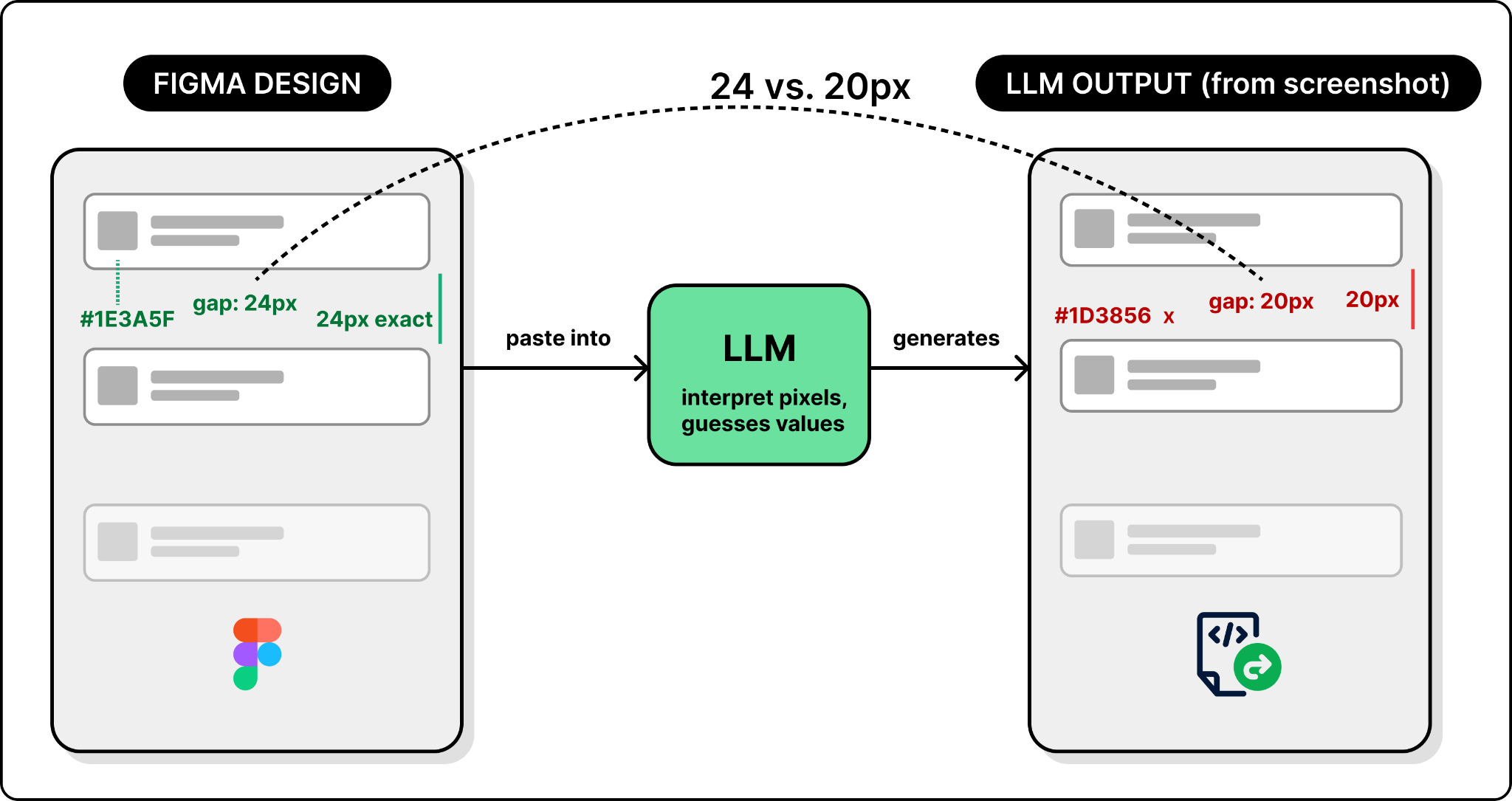
So screenshots give the model a visual reference but no precise values. The next instinct: go in the opposite direction and hand it all the data.
Approach 2: Get design JSON via Figma's REST API
Figma exposes a REST API that returns a file's entire structure as JSON — every node, property, and style. Now the LLM has real numbers, not pixels.
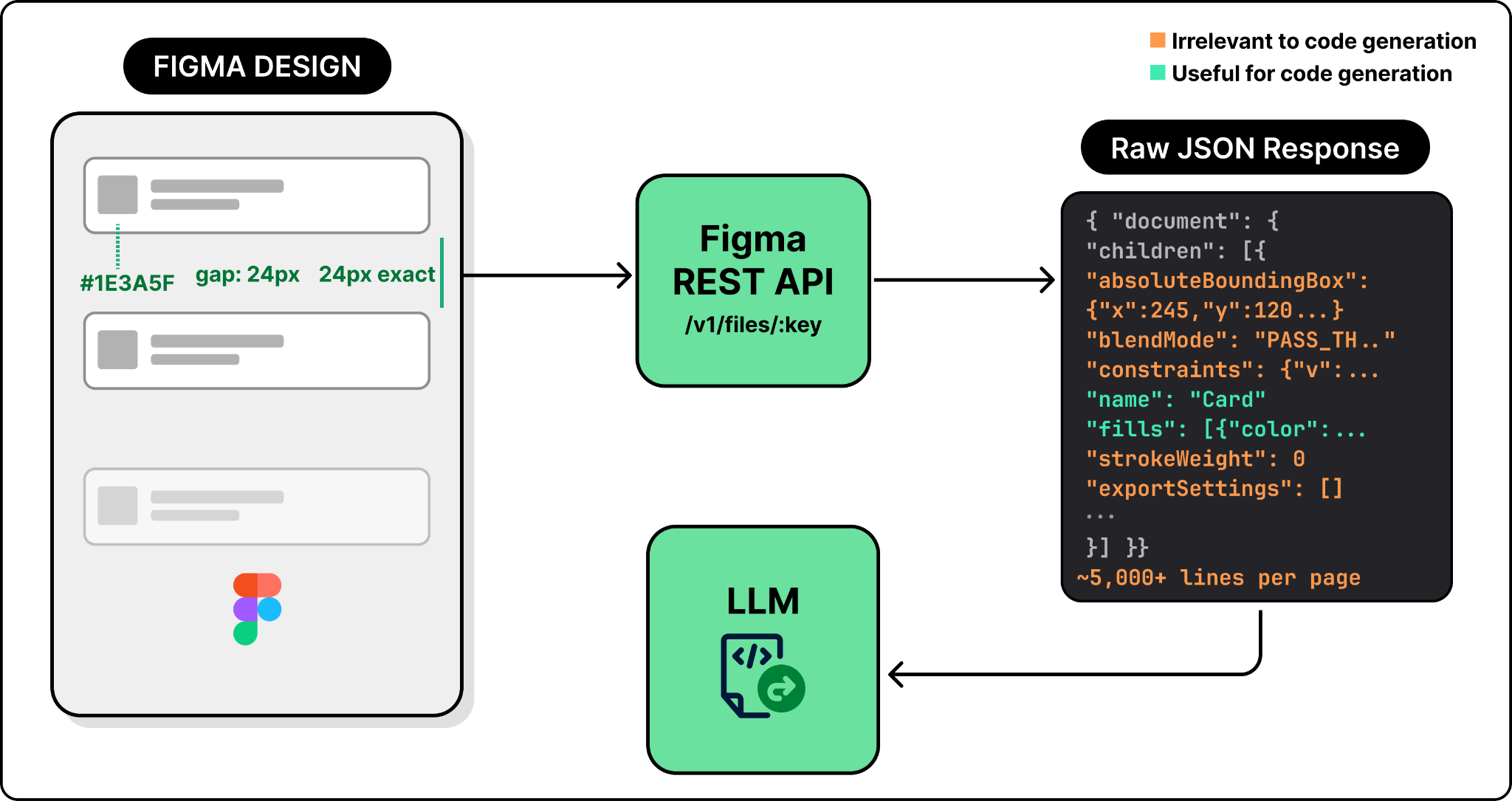
The new problem: there's far too much of it. A single Figma page can produce thousands of lines of JSON stuffed with absolute pixel coordinates, blend modes, export settings, internal layout rules, effects, and other metadata that have nothing to do with building a UI. Dumping all that into the prompt either blows past the LLM's context window or, even when it fits, drowns the model in noise that degrades the output.
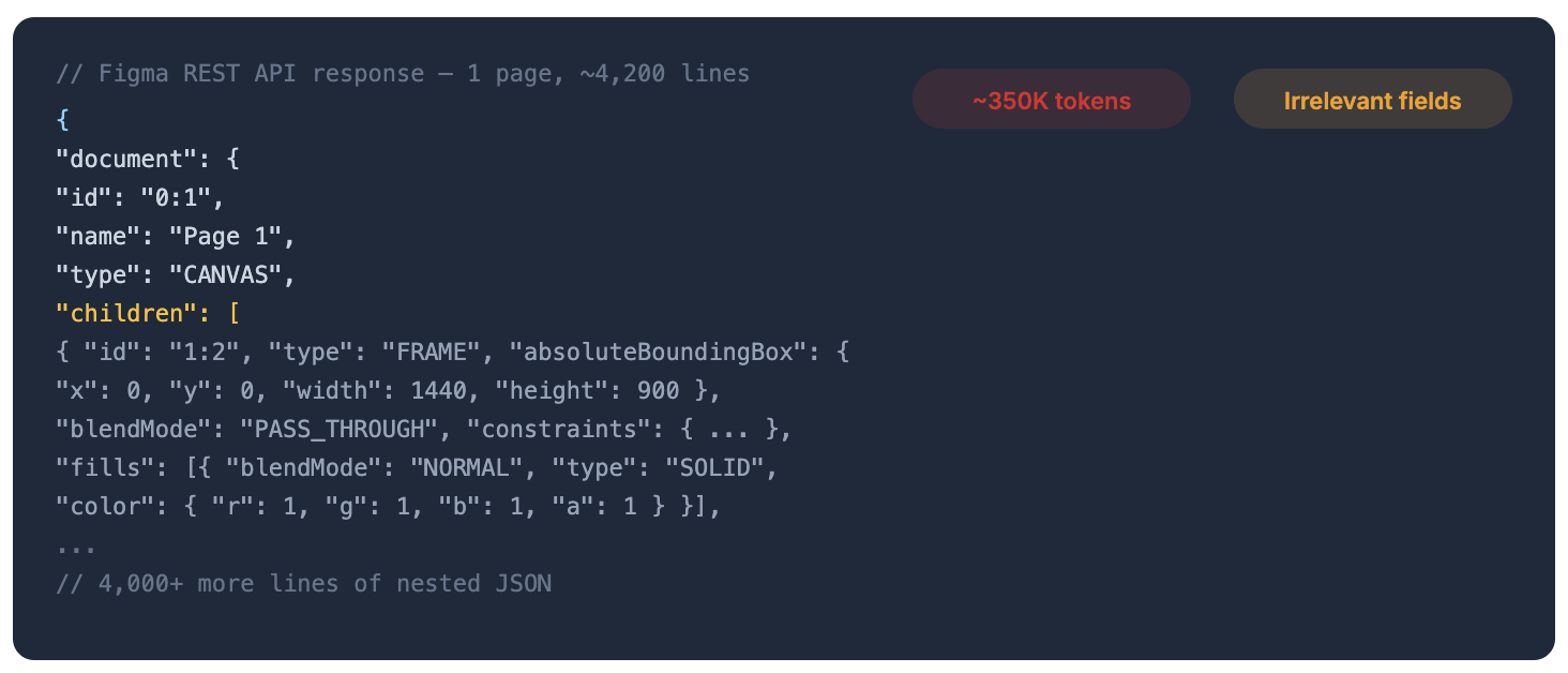
Neither extreme works. Screenshots lack precision; raw JSON has precision but is mostly noise. What you actually want is structured design data that preserves exact values (colors, spacing, component names) but strips everything irrelevant to code generation.
The middle ground: Figma's MCP server
That's exactly what the MCP server does. MCP (Model Context Protocol) is a standard that defines how AI agents discover and call external tools — think of it as a USB plug for tools that LLMs can speak to.
Figma's MCP server pulls raw design data from the REST API, filters out the noise, and reshapes what remains into a clean representation that maps to how a developer thinks about UI:
- Pixel positions become layout relationships ("centered inside its parent") instead of absolute x/y coordinates.
- Raw hex colors become design token references like
brand-blueinstead of#3B82F6. - Deeply nested Figma layers get flattened to match what a developer would actually build.
The result is a compact, token-efficient context the LLM can act on directly.
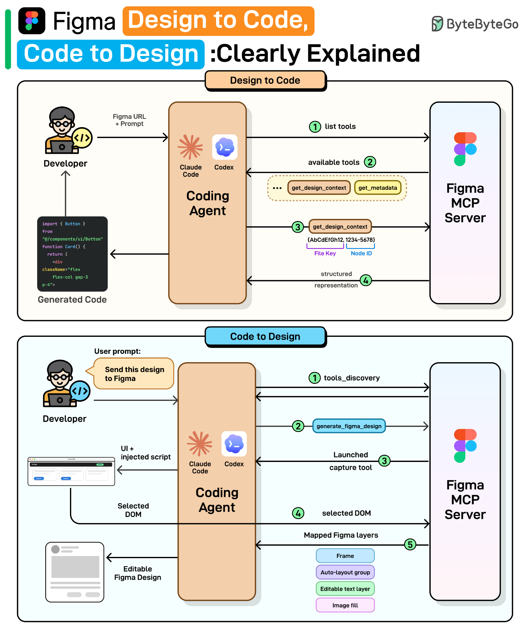
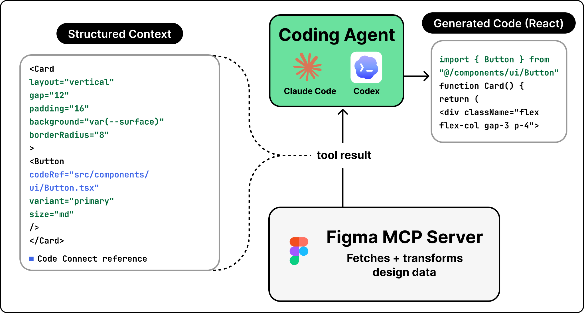
Workflow 1: Design → Code
The flow starts when a developer selects a frame in Figma, copies its URL, pastes it into Claude Code or Codex, and prompts something like "Implement this design." The agent then writes working code matching the design. Here's what happens behind the scenes.
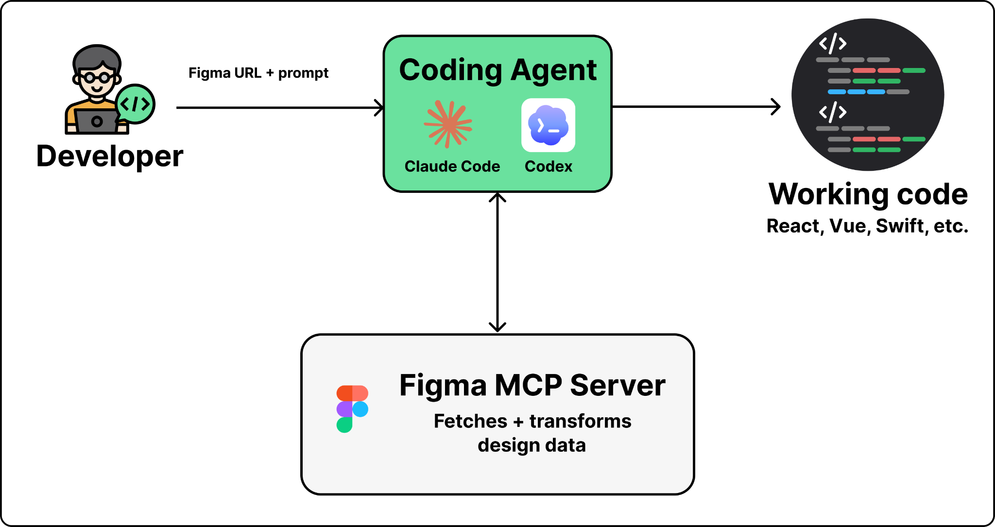
Four steps. The first two are generic MCP mechanics; the last two are where Figma's engineering earns its keep.
Step 1 — The agent discovers available tools. When the agent first connects to the MCP server, it gets back a list of tools: get_design_context, get_screenshot, get_metadata, and others. Each one comes with a name, description, and parameter schema. The agent doesn't know how Figma works internally — it reads these descriptions like a developer reads API docs and decides which tool to call based on the user's prompt.
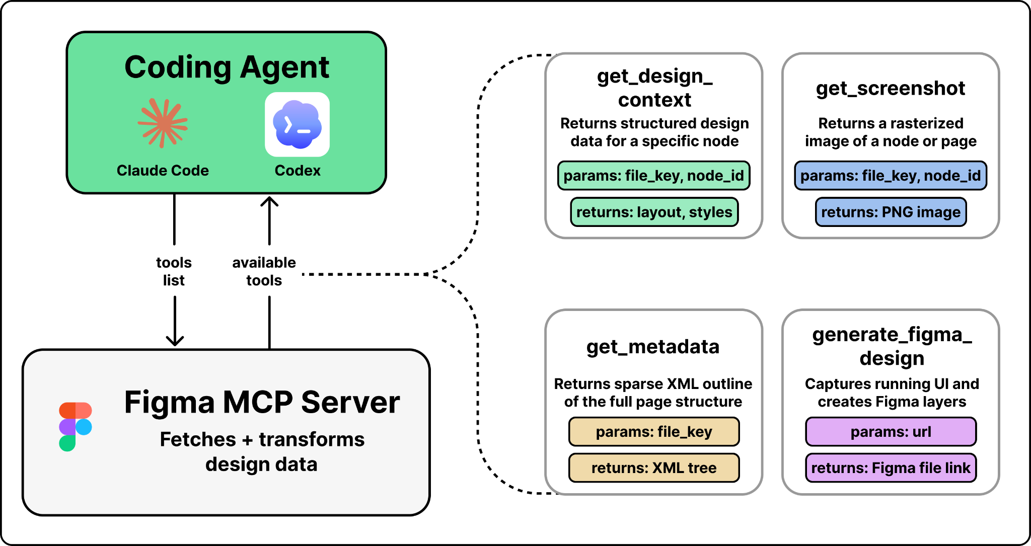
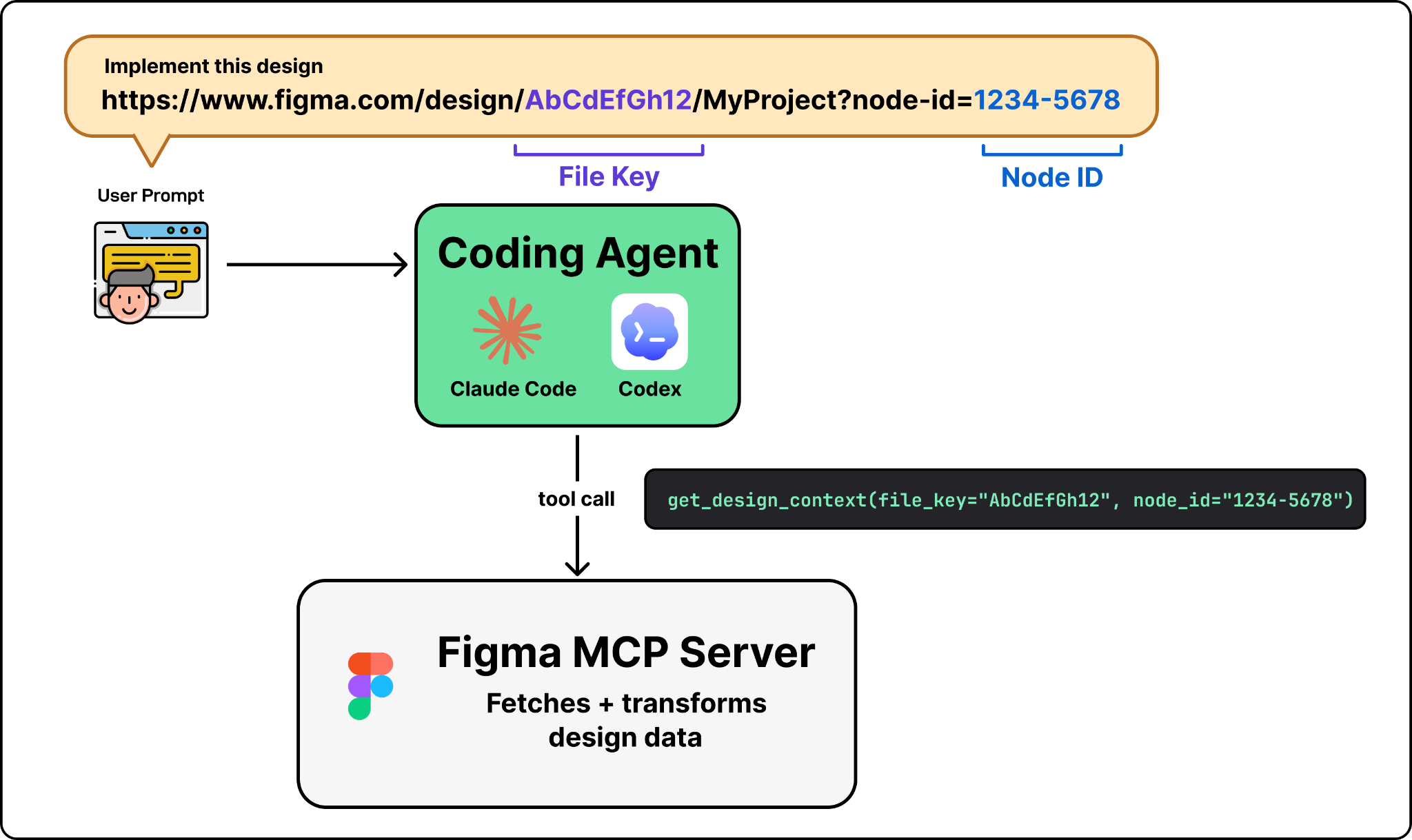
Step 2 — The agent prepares arguments and calls the tool. For "implement this design," the agent picks get_design_context, which needs a file key and a node ID. It parses both out of the Figma URL the user pasted and fires the call.
Step 3 — The request hits Figma's backend. The call travels to mcp.figma.com/mcp over Streamable HTTP. The server authenticates and asks Figma's internal services for the design data: node trees, component properties, styles, variable definitions.
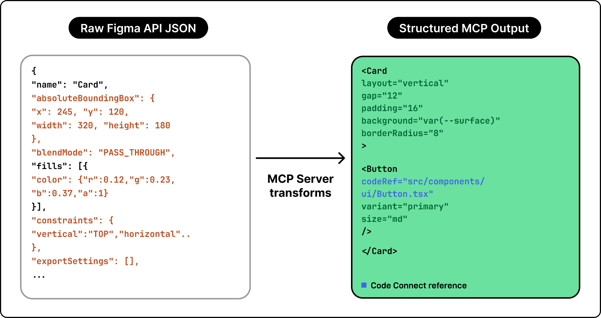
Step 4 — Transform raw design data into LLM-friendly context. This is where the real engineering happens. The MCP server takes the raw JSON and converts it into a representation that mirrors how a developer would build the UI:
- Pixel positions → layout relationships ("this element is centered inside its parent").
- Raw color codes → design token references like
brand-blue. - Deeply nested layers → simplified to match the visible structure.
- Components → enriched with code mappings. If a Figma button component has been mapped to
src/components/ui/Button.tsxvia Code Connect, that path appears in the output. The LLM reuses the existing component instead of reinventing it.
The output is framed as React + Tailwind by default (the most common stack), but it's a structured representation, not generated code. The LLM consumes that representation and produces actual code in whatever framework the developer asked for.
Workflow 2: Code → Design
Design-to-code is only half the loop. In practice, code drifts ahead of design: a developer ships a feature, tweaks layouts based on user feedback, adds a new section, and the Figma file no longer matches production. Code → design closes that gap. The developer types "send this to Figma" in Claude Code, and a few seconds later the live UI shows up in Figma — not as a flat screenshot, but as fully editable layers with auto-layout, editable text, and separate components.
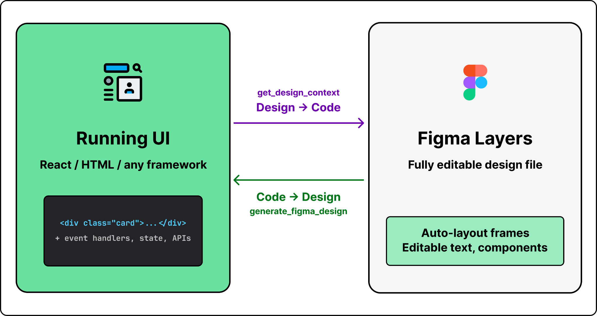
This is powered by one key MCP tool: generate_figma_design.
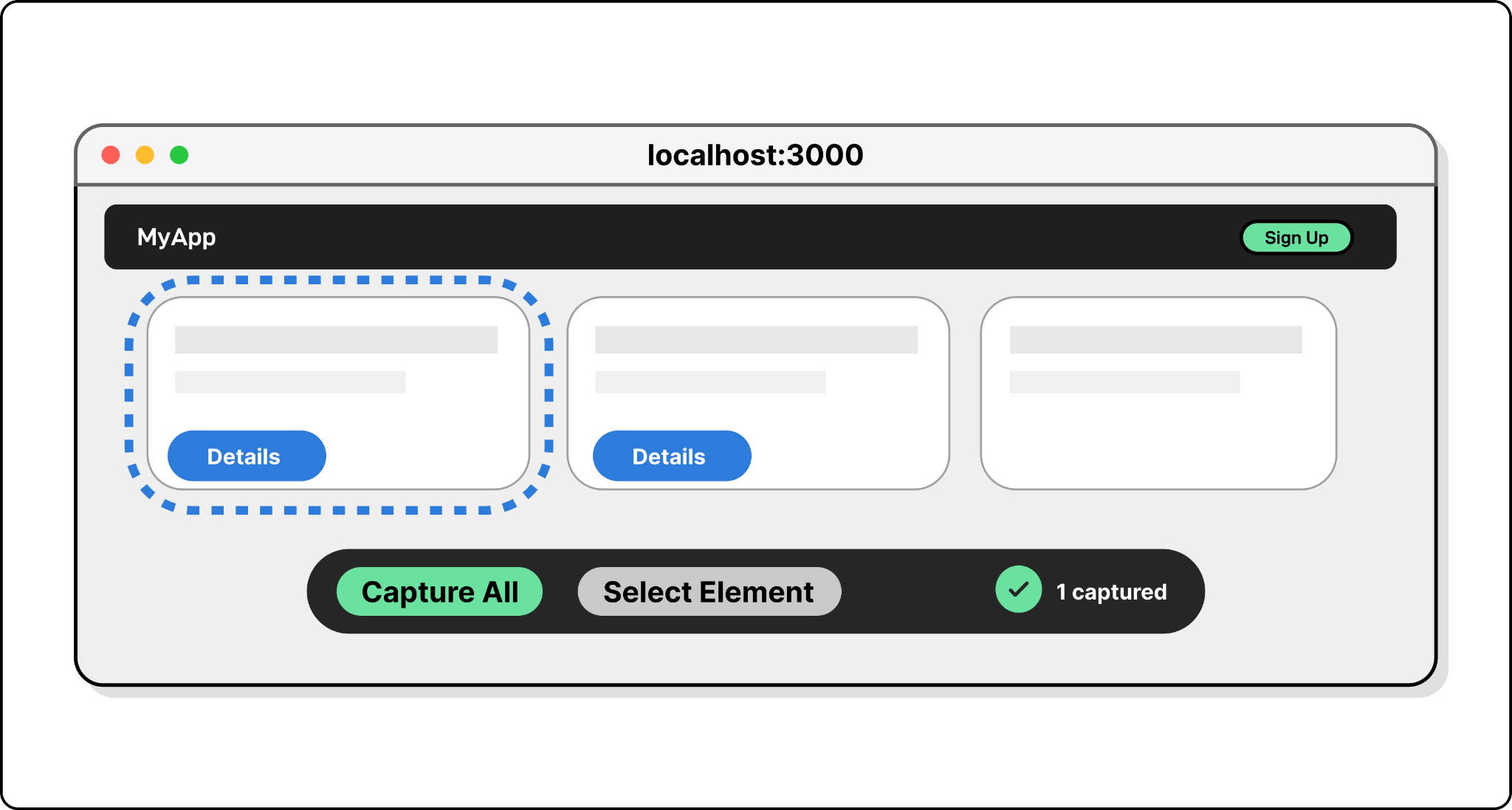
Step 1 — The tool launches a capture script. The agent calls generate_figma_design. The tool opens the target URL in a browser and injects a JavaScript capture script. For a local dev server it connects directly; for staging or production URLs it uses a browser automation library like Playwright to open the page and inject the script programmatically. When the browser opens, the developer sees the running UI plus a capture toolbar overlay. An initial capture happens automatically; from there the developer can grab the whole screen or pick specific elements.
Step 2 — The script reads the DOM (not pixels). This is the critical move. When the user picks a UI region, the injected script doesn't take a screenshot — it walks the live DOM tree, extracting computed styles, layout properties, text content, and image sources for every visible element. Crucially, it preserves the parent-child hierarchy: a flex container with three children stays a container with three children, not a flat collection of boxes. Capturing structure (rather than pixels) is what makes the output editable in Figma later.
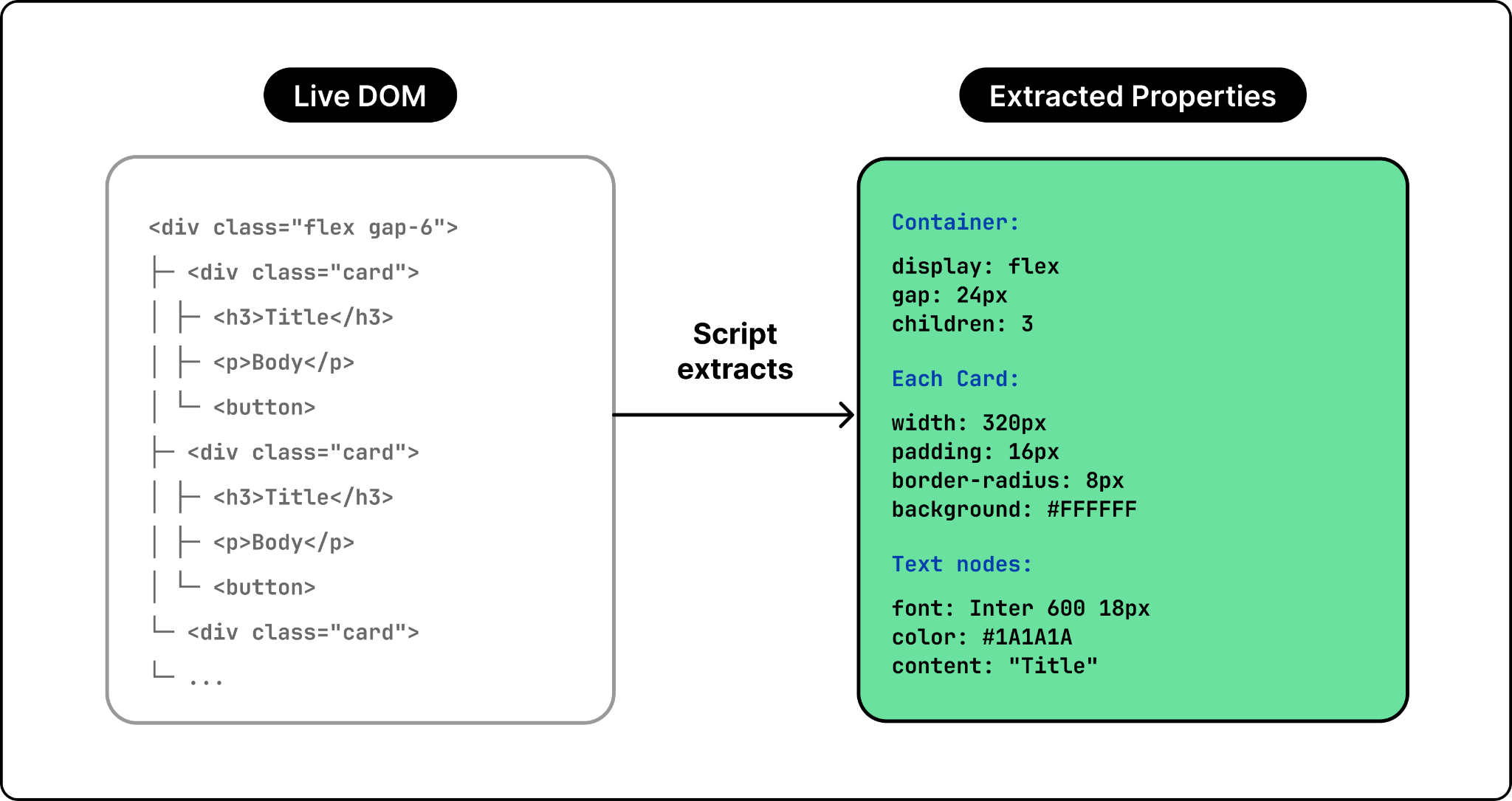
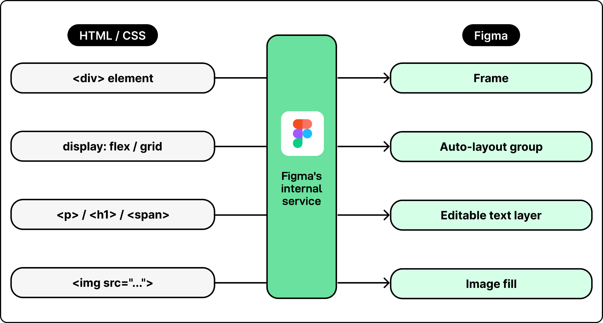
Step 3 — DOM data becomes Figma layers. The captured DOM gets sent to Figma's backend and reconstructed as native design layers:
- Each HTML element → a Figma frame or shape.
- CSS flexbox and grid layouts → Figma auto-layout groups.
- Text nodes → editable Figma text layers with the right font, size, weight, color.
- Images → extracted and embedded as image fills.
Engineering challenges (and how Figma addressed them)
Making both workflows work reliably across millions of Figma files, multiple coding agents, and real-world design systems surfaces a different class of problems.
Challenge 1: Context window limits
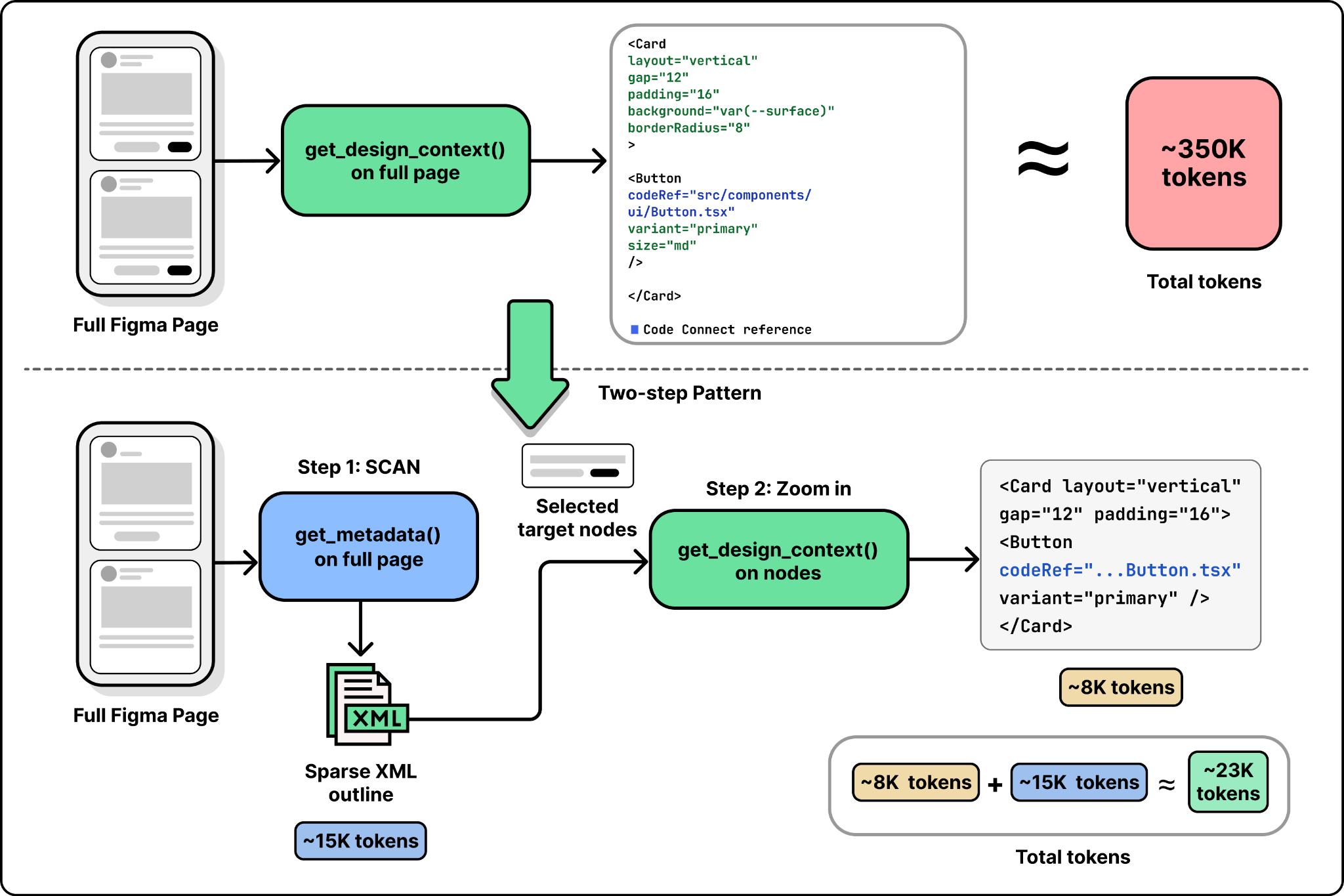
LLMs have fixed context windows, so token count is a hard constraint. A complex Figma page can produce far more design data than an agent can swallow in one call. Claude Code, for instance, defaults to a 25,000-token cap on MCP tool responses. Calling get_design_context on an entire page (rather than a specific node) easily blows past that and gets truncated.
Figma's fix is the get_metadata tool, which returns a sparse XML outline of the file instead of the full styled representation. The pattern is "scan first, zoom in": call get_metadata to see the structure, identify the specific nodes you care about, then call get_design_context only on those nodes. This isn't unique to Figma — anyone building an MCP server over large structured data (codebases, doc stores, design files) ends up rediscovering the same two-step pattern.
Challenge 2: Component mapping
By default the coding agent has no idea which Figma components correspond to which code components. Without that mapping, it'll waste time grepping the codebase for matches — and if it doesn't find one, it'll just create a new component from scratch. Multiply that across every reusable component in a design system and the generated code drifts from the codebase fast.
Figma addresses this with Code Connect, which lets teams create explicit mappings between Figma node IDs and code file paths. Once configured, the MCP server includes those mappings in its responses, and the agent reuses the real component instead of guessing.
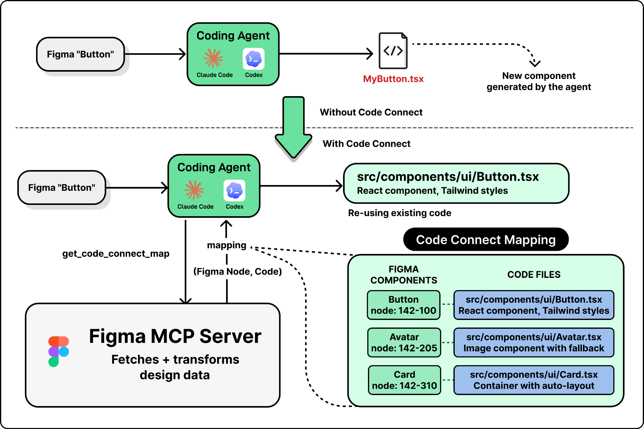
The catch: Code Connect requires manual setup — someone has to create and maintain those mappings. Figma is reducing the friction with helpers like get_code_connect_suggestions, which auto-detects and proposes mappings, but the quality of generated code is still directly tied to how much the team has invested in connecting their design system to their codebase.
Challenge 3: The lossy roundtrip
The bidirectional loop sounds seamless, but each handoff loses information:
- Design → code: structured context captures layout, styles, and component references — but not business logic, event handlers, state management, or API calls. The agent fills those in when generating code.
- Code → design (via
generate_figma_design): the DOM walk captures visual structure and styles but strips everything that isn't visible — React state, API integration, route handling.
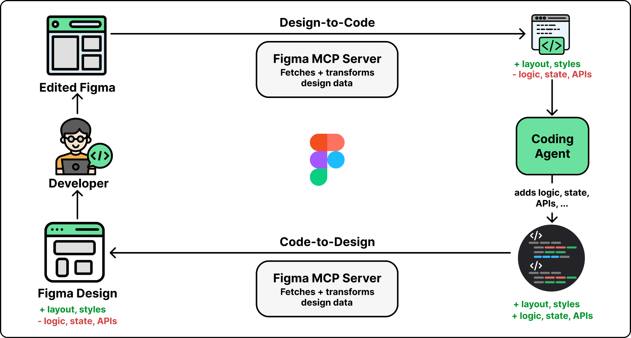
The consequence: every roundtrip requires re-inference. When a designer modifies a captured UI in Figma and the developer pulls it back into code, the agent translates visual decisions into implementation from scratch — it has no access to the previous version of the code. Code Connect mappings preserve the link between design components and their code implementations across roundtrips, but non-visual logic still has to be re-added each time.
Challenge 4: Serving multiple agents with different capabilities
Figma's MCP server doesn't serve a single client. It serves Claude Code, Cursor, Codex, and any other MCP-compatible tool — and each agent has different context window sizes, different tool-calling behaviors, and different sophistication when it comes to chaining multiple tool calls. A workflow that flows nicely in one agent may stutter in another.
generate_figma_design, for instance, is now available in Claude Code and Codex but not everywhere yet, because code-to-design needs tighter browser integration (script injection, capture toolbar, multi-screen state) than most agents currently support. Building an MCP server that works well across a growing ecosystem of agents with varying capabilities is one of the harder ongoing problems in this space.
A recent evolution: Figma has opened the canvas itself to agents via the use_figma MCP tool, so agents can not only read design context but actively modify and create designs — editing the canvas directly and creating new assets using your existing components and variables.
Takeaways
The hardest part of building an MCP server isn't implementing the protocol. It's the design decisions Figma's team had to wrestle with:
- What context to include and what to leave out (filter noise, keep precision).
- How to structure it so LLMs can reason about it (layout relationships and design tokens, not raw pixels and hex codes).
- How to stay within token budgets (the scan-first, zoom-in pattern with a sparse outline tool plus a detailed node tool).
- How to bridge the gap between visual data and code semantics (Code Connect mappings to keep components coherent).
These are the choices that separate a useful MCP server from one that just wraps an existing API — and they generalize to anyone building an MCP server for any complex domain.
Author
ByteByteGo
Continued reading
Keep your momentum
MKT1 Newsletter
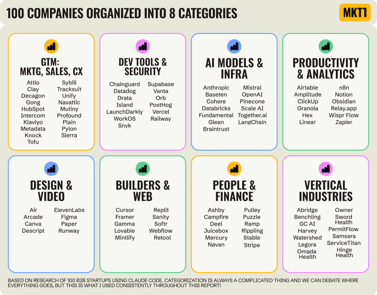
100 B2B Startups, 100+ Stats, and 14 Graphs on Web, Social, and Content
This is Part 2 of MKT1's three-part State of B2B Marketing Report. Where Part 1 looked at teams and leadership , Part 2 turns to what marketing teams are actually doing — what their websites look like, how they use social, and what "content fuel" they're producing. Emily Kramer u
Apr 28 · 10m
Lenny's Newsletter (Lenny's Podcast)
Why Half of Product Managers Are in Trouble — Nikhyl Singhal on the AI Reinvention Threshold
Nikhyl Singhal is a serial founder and a former senior product executive at Meta, Google, and Credit Karma . Today he runs The Skip ( skip.show (https://skip.show)), a community for senior product leaders, plus offshoots like Skip Community , Skip Coach , and Skip.help . Lenny de
Apr 27 · 7m

The AI Corner
The AI Agent That Thinks Like Jensen Huang, Elon Musk, and Dario Amodei
Dominguez opens with a claim that is easy to skim past but worth stopping on: the difference between elite founders and everyone else is not raw IQ or speed — it is that each of them has internalized a repeatable mental procedure they run on every important decision. The procedur
Apr 27 · 6m